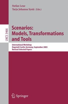
Visual notations and languages continue to play a pivotal role ? in the design of complex software systems. In many cases visual notations are used to – scribe usage or interaction scenarios of software systems or their components. While representing scenarios using a visual notation is not the only possibility, a vast majority of scenario description languages is visual. Scenarios are used in telecommunications as Message Sequence Charts, in object-oriented system design as Sequence Diagrams, in reverse engineering as execution traces, and in requirements engineering as, for example, Use Case Maps or Life Sequence Charts. These techniques are used to capture requirements, to capture use cases in system documentation, to specify test cases, or to visualize runs of existing systems. They are often employed to represent concurrent systems that int- act via message passing or method invocation. In telecommunications, for more than 15 years the International Telecommunication Union has standardized the Message Sequence Charts (MSCs) notation in its recommendation Z. 120. More recently, with the emergence of UML as a predominant software design meth- ology, there has been special interest in the development of the sequence d- gram notation. As a result, the most recent version, 2. 0, of UML encompasses the Message Sequence Chart notation, including its hierarchical modeling f- tures. Other scenario-?avored diagrams in UML 2. 0 include activity diagrams and timing diagrams.
Engineering
{PDF} Scenarios: Models, Transformations and Tools: International Workshop, Dagstuhl Castle, Germany, September 7-12, 2003, Revised Selected Papers ?ystein Haugen, Knut Eilif Husa, Ragnhild Kobro Runde, Ketil St?len (auth.), Stefan Leue, Tarja Johanna Syst? (eds.)
$19.99


Reviews
There are no reviews yet.